ALLOY WHEEL TECHNICAL INFORMATION
DIMENSIONS
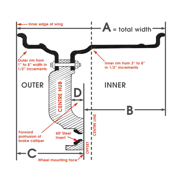
Measurement Diagram
‘A’ = TOTAL WIDTH OF WHEEL
‘B’ = BOLT UP FACE INTO CAR
‘C’ = BOLT UP FACE TO INNER EDGE OF WING
‘D’ = FORWARD PROTRUSION OF BRAKE CALIPER
Three piece wheels consist of a computer spun inner and outer rim section and a centre hub. When selecting your wheel size it is important to remember that our wheel sizes given are tyre seat to tyre seat.
EXAMPLE: IF YOU ORDER A 7.0 x 15” WHEEL DIMENSION ‘A’ = 8.0”
OFFSET
The amount of wheel going INTO the car from the wheel centreline is POSITIVE.
The amount of wheel moving OUT of the car from the centreline is NEGATIVE.
The measurement diagram shows a POSITIVE offset, along with dimensions ‘A’ ‘B’ ‘C’ and ‘D’.
The measurement from the wheel mounting face to the outside of the car STATE C DIMENSION.
The measurement to check the brake caliper protrusion forwards of the wheel mounting face STATE D DIMENSION.
Correct Measurement Method
Dimension “A” is total width of the wheel (edge to edge) this is 1.0″ wider than the actual wheel size (tyre bead to tyre bead).
For example if you are ordering an 8.0″ X 15″ wheel (tyre bead to tyre bead) Dimension “A” will be 9.0″ (edge to edge).
STEP 1
Get the car jacked up and lowered back down to ride height on the suspension so the car is at ride height.
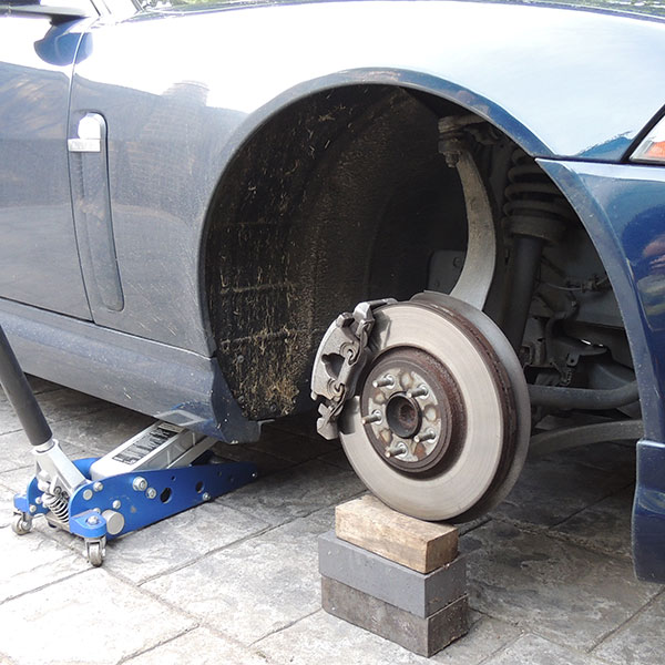
Jack up the car – lower to ride height
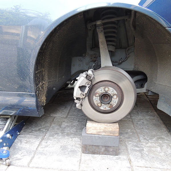
Support on the suspension so the car is at ride height
STEP 2, MEASURING DIMENSION B
Use a straight edge (steel rule or spirit level) and place it against it the hub face on the car running vertical from top to bottom (photo measurement B-1).
Then with a steel rule (best) or tape measure, measure the distance from the back edge of your straight edge (photo measurement B-A) – to the first fouling point a wheel would come into contact with, this usually the shock absorber or spring/upright (photo measurement B-B).
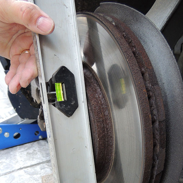
Measurement B-1
Measurement B-A
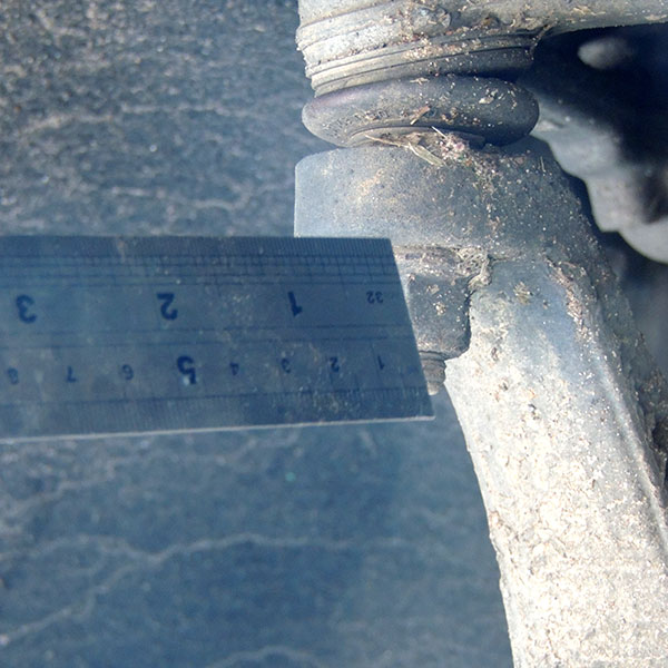
Measurement B-B
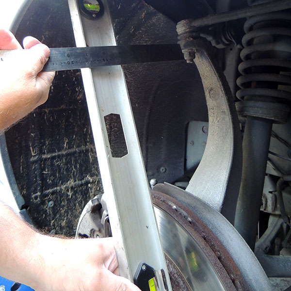
Measurement B full setup
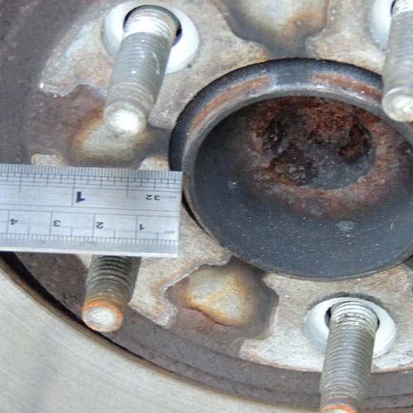
STEP 3, MEASURING DIMENSION C
Using a spirit level place it against the car in the centre of the wheel arch in a vertical position and ensure it straight (90 deg to the floor) and touching the bodyline of the car, then measure back to the hub face on the car from the straight edge, you can also use a plumb line hung from the centre of the wheel arch, (photos measurement C and measurement C-A).
Measure the thickness of the wheel arch edge with a steel rule/tape measure as shown, (photo Arch Width).
Measurement C
Measurement C-A
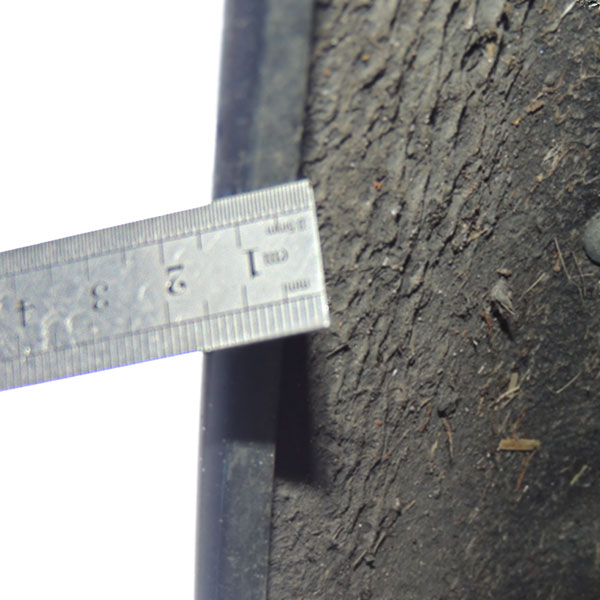
Measurement – Arch Width
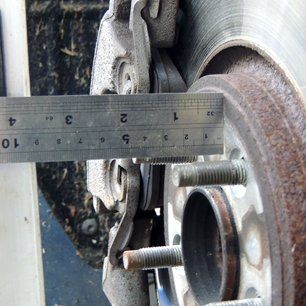
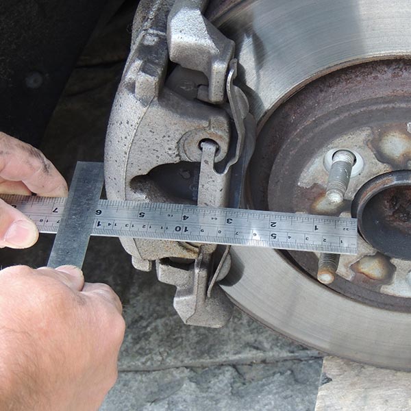
STEP 4, MEASURING DIMENSION D
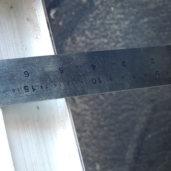
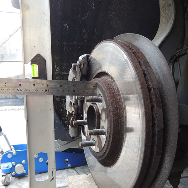
Place a straight edge across the face of the brake calliper running horizontally/parallel with the hub face and then measure back to the hub face, (photo measurement D and measurement D-A).
Measurement D
Measurement D-A
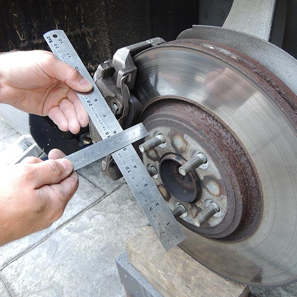
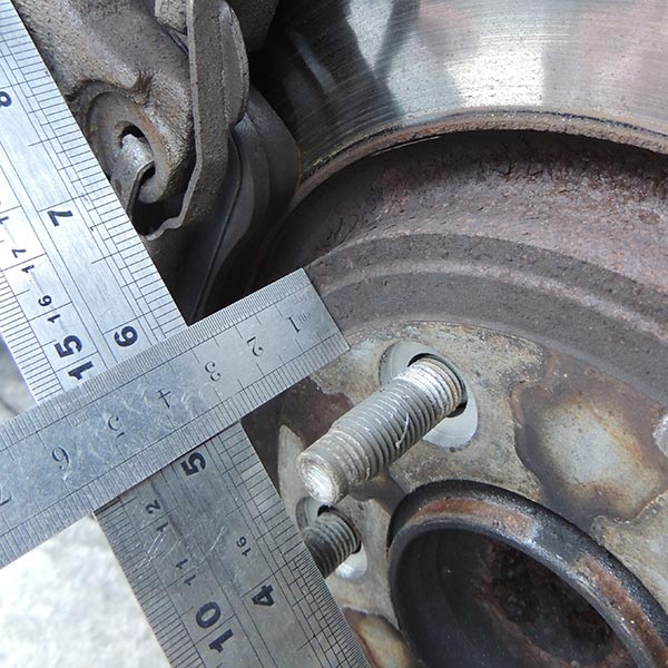
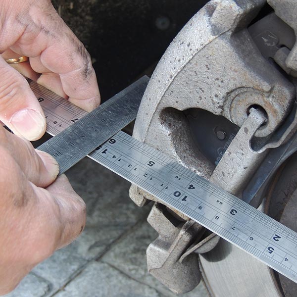
BRAKE CALLIPER RADIUS
A measurement we sometimes require is the brake calliper radius, to measure this place a straight edge against the outside edge of the calliper at the furthest point from the centre of the hub, (photo Calliper Radius – Full).
Take a steel rule and place it across the face of the calliper so it meets the edge of the hub location in the centre of the hub (photo Calliper Radius – 1).
Where the rule meets the straight edge will give you the radius of the brake calliper (photo Calliper Radius – 2).
Caliper Radius – Full
Caliper Radius – 1
Caliper Radius – 2
PCD (PITCH CIRCLE DIAMETER)
Pitch Circle Diameter stud patterns
PCD 3 Stud
PCD 4 Stud
PCD 5 Stud
We can accommodate larger PCD sizes on our Billet centres. Example 5x130mm plus. We can also do CENTRE LOCK in some Cast and Billet styles.
If you require further information on any of the above, please give us a call and we will be happy to help.
Centrelock Dimensions
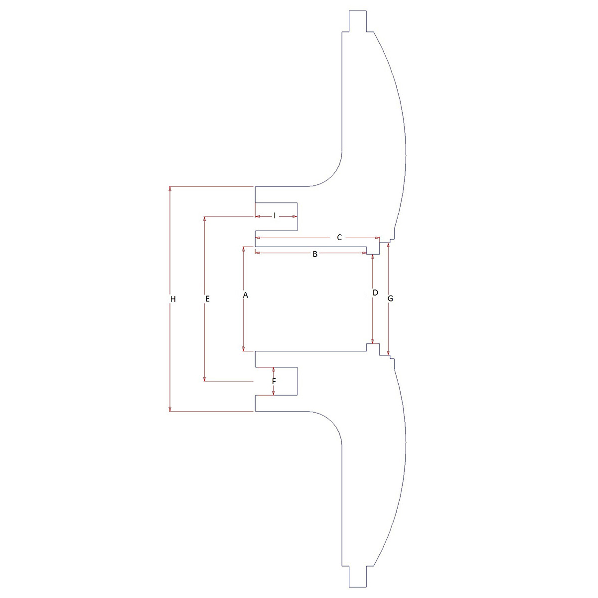
Centrelock Flat Seating Dimensions
‘A’ = LOCATION DIAMETER
‘B’ = LOCATION DEPTH
‘C’ = NAVE THICKNESS
‘D’ = SHAFT CLEARANCE
‘E’ = PCD AND NUMBER OF HOLES
‘F’ = PCD HOLE DIAMETER
‘G’ = NUT/WASHER FLAT SEATING DIAMETER
‘H’ = MOUNTING FACE DIAMETER
‘I’ = PCD HOLE DEPTH
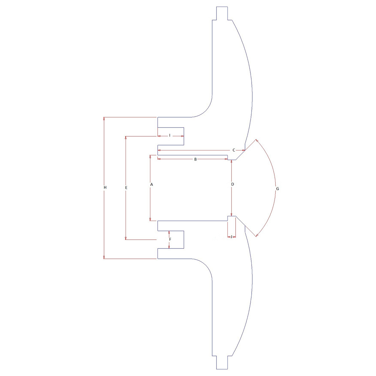
Centrelock Dimensions
‘A’ = LOCATION DIAMETER
‘B’ = LOCATION DEPTH CLEARANCE
‘C’ = NAVE THICKNESS
‘D’ = SHAFT CLEARANCE
‘E’ = PCD AND NUMBER OF HOLES
‘F’ = PCD HOLE DIAMETER
‘G’ = NUT SEATING ANGLE
‘H’ = MOUNTING FACE DIAMETER
‘I’ = PCD HOLE DEPTH
‘J’ = RETURN DEPTH
SPLIT RIM WHEELS
Every set of wheels we manufacture are MADE TO ORDER to suit your vehicle application. We do not keep finished wheels in stock.
A split rim wheel consists of an Outer Rim, Centre Hub and Inner Rim. Dependent on the fitment needed these three sections can be assembled either as a FRONT MOUNT construction or SANDWICH MOUNT construction.
We can supply some wheels with the perimeter bolts hidden – CLASSIC BUILD (Front mount construction only).
All wheels are dispatched fully assembled and ready to have tyres fitted. They come complete with fixing nuts or bolts and centre caps, unless you have ordered Lockplates or Spinners. All Image Wheels have been constructed to either British BS AU:50 or T.U.V standards.
CENTRE HUB
Available in either cast or billet material
CAST AND HEAT TREATED STYLE CENTRES
The rim sections are the same for the cast and billet 3 piece wheels it is only the centres that are different. The cast centres are of the original race proven pedigree and concept of the image wheels range since 1987. We produce a range of classic /retro and modern styles. They are then heat treated ready to be machined to fit the rim sections and customer requirements. We cast them in the foundry from prime alloy ingots. Metal is poured into the mould creating the style ready to be machined to fit the rim sections and customers vehicle requirements.
BILLET CENTRES
Billet wheels as the cast use the same rim sections only the centre is made of billet. We make them from compressed prime heat treated billet creating a stronger grain structure. The designs are computer generated and stress tested prior to manufacture. We then produce them on our C.N.C machines to create the style and vehicle fitments. Because of the type of alloy and the manufacturing costs it does make them more expensive than the cast centres. The main advantage for competition use is the weight saving over the cast centres like for like size and strength this would be approx. 20-25%. The other advantage for road and show cars is you can have it polished to a mirror finish and we can design and produce almost any size fitment and style.
All our wheels are designed and tested using Finite element analysis with state of the art computer techniques.
OUTER RIM
This component is flow formed from prime aluminium sheet. Sizes start at 1.0” wide and increase in half inch increments.
Standard supply is POLISHED finish, but you can request on your order sheet for the rims to be ANODIZED. (Extra cost. £30 per item.)
INNER RIM
This component is also flow formed from prime aluminium sheet. Sizes start as 3.5” wide and increase in half inch increments.
Standard supply is ANODIZED finish. You can have it supplied PAINTED at no extra cost, just stipulate this on your order. The rim can also be POLISHED at an extra cost (POA).